UHF Radio Links for GNSS RTK: Bandwidth, Modulation and Protocols Explained
A practical surveyor's guide to channel spacing, GMSK vs 4FSK, FEC, TRIMTALK, SATEL, Pacific Crest, and getting the most range out of your base radio.
Why UHF Still Matters in 2026
NTRIP over cellular has become the default RTK correction method for surveyors operating near towns, highways, and provincial CORS coverage. So why bother with a UHF base radio? Because cellular runs out — and when it does, your fix runs out with it. Highway corridors between towns, mining sites, hydro right-of-ways, forestry blocks, agricultural fields, and most of northern Canada all share one thing: no LTE bars. UHF radio remains the most reliable way to get RTK corrections from a base over a known control point to one or many rovers within 10–30 km, with no subscription, no SIM, and latency under 100 ms.
The moment you reach for that radio, though, you walk into a thicket of acronyms — GMSK, 4FSK, TRIMTALK 450S, SATEL 3AS, Pacific Crest, FEC, scrambling, 12.5 kHz, 25 kHz. Pick the wrong combination on either end and your rover sits on float forever, even though everything looks "connected." This guide walks through every layer in plain language, with the specific settings real surveyors actually choose in real conditions.
This post is the radio-link companion to our Survey-Grade GNSS Corrections and Data Formats Explained guide. That post covers what the base sends (RTCM, MSM, CMRx). This one covers how it gets to the rover when there is no cellular network to lean on.
Frequency Bands & Range
UHF (403–473 MHz) — the survey standard
Almost every survey-grade RTK radio operates in UHF, typically 410–470 MHz. The wavelength of around 67 cm strikes the sweet spot between long-range propagation and a reasonably small antenna. Signals travel well over rolling terrain, partially diffract around obstacles, and penetrate light vegetation better than higher frequencies.
Practical range: 5–30 km depending on power, antenna height, terrain and modulation. Typical transmit power: 1–5 W for portable rovers; 25–35 W for fixed bases on long projects, or for everyday setups using external base radios paired with integrated rovers. Channels: survey radios operate on pre-programmed UHF channels supplied by your dealer.
900 MHz ISM — shorter range, crowded spectrum
The 902–928 MHz ISM band is historically popular for spread-spectrum survey radios. The trade-offs are shorter range (typically 1–5 km), more crowded spectrum (cordless phones, baby monitors, LoRa devices), and higher path loss through trees and structures. For most professional Canadian surveying work, UHF wins on range and stability. 900 MHz finds its niche in short-baseline UAV operations and small-fleet machine control.
VHF (150–174 MHz) is no longer common in modern survey radios. Older systems used it for very long range, but multipath behaviour and antenna size made it impractical for everyday surveying. If you inherit a VHF base, treat it as legacy gear.
Channel Spacing: 12.5 vs 25 kHz
A UHF "channel" is a slice of spectrum reserved for one transmitter at a time. Two widths are common in survey radios, and your channel width sets the ceiling for everything else — modulation, data rate, and how much correction data fits in one second.
What "channel width" actually means
Your radio doesn't get a single point in spectrum — it gets a slice centered on the assigned frequency. A 25 kHz channel at 450 MHz runs from 449.9875 MHz to 450.0125 MHz — exactly 12.5 kHz on each side of center. A 12.5 kHz channel halves that. The number describes the width of your slice, not anything beyond the carrier.

Same center frequency, different slice widths. The channel extends symmetrically around 450 MHz.
You need a slice rather than a single point because the moment you modulate the carrier to encode data, the signal spreads into adjacent frequencies — fundamental signal physics. The channel width is the guard rail keeping that spread inside your assigned slice instead of bleeding into the neighbor's channel. A wider slice gives your modulation more room, which is why 25 kHz channels carry more data than 12.5 kHz ones.
| Channel width | Over-the-air rate (4FSK) | Typical use |
|---|---|---|
| 12.5 kHz (narrowband) | ~9600 bps | The default for most modern survey radios and new channel assignments in North America |
| 25 kHz (wideband) | ~19,200 bps | Roughly double the data capacity. If it is allowed on your channel and your receiver supports it, take it |
12.5 kHz is the practical default for most survey radios in everyday use. The bandwidth pressure that drives the rest of this guide is largely about fitting modern multi-constellation correction streams through that 12.5 kHz constraint. If your channel allocation and equipment both support 25 kHz, much of that pressure disappears — see the Bandwidth section below for what twice the channel actually buys you.
Modulation: GMSK, 4FSK, 8FSK, 16FSK
Modulation is how the radio encodes ones and zeros into changes in the carrier wave. Different schemes balance data rate, sensitivity, and heat. Here is what each one means for a survey radio.
GMSK — best sensitivity, slower
Gaussian Minimum Shift Keying produces a continuous-phase signal with very low out-of-band emission. It is robust at the noise floor, runs cool, and recovers weak signals well. The trade-off: lower throughput per Hz of channel.
Throughput: 4800–9600 bps in 12.5 kHz, up to 19,200 bps in 25 kHz, depending on the protocol implementation.
Choose it when: long-range or marginal-signal projects; range matters more than throughput.
4FSK — modern default
4FSK uses four discrete frequencies, encoding two bits per symbol — roughly twice the data rate of GMSK at the same protocol layer. Shorter transmit bursts mean less heat. The trade-off: slightly lower sensitivity at the noise floor than GMSK.
Throughput: 9600 bps in 12.5 kHz, 19,200 bps in 25 kHz (FEC off; FEC on reduces the rate by about 25%).
Choose it when: default for any link with healthy signal margin and modern multi-constellation corrections.
8FSK and 16FSK — more bits, less range
SATEL's modern transceivers (TR4+, EASy+) support 8FSK (three bits/symbol) and 16FSK (four bits/symbol). Each extra bit per symbol adds throughput but raises the signal-to-noise requirement sharply — moving from 4FSK to 16FSK can reduce practical range by half.
Throughput: up to 14,400 bps in 12.5 kHz, 28,800 bps in 25 kHz on SATEL EASy+ class radios.
Choose it when: short-range, data-heavy applications on a known good link. Not the right choice for marginal long-range work.

Same channel width, more tones. GMSK uses 2; 16FSK has to fit 16 in the same slice.
The same channel width has to fit every tone the modulation uses. As you add more tones to encode more bits per symbol, they sit closer together. Over longer distances the signal weakens and ambient noise becomes proportionally larger — the receiver has a much harder time telling closely-spaced tones apart. In 16FSK, two adjacent tones that look distinct on a strong signal start blurring into each other once the link gets noisy, and the receiver drops out at distances where GMSK's two well-separated tones would still resolve cleanly. That is the physics behind the range trade-off — not transmit power, but tone discrimination at the receiver.
Modulation at a glance
| Modulation | 12.5 kHz | 25 kHz | Sensitivity (range) |
|---|---|---|---|
| GMSK | 4800–9600 bps | 9600–19,200 bps | Best |
| 4FSK | 9600 bps | 19,200 bps | Very good |
| 8FSK | 14,400 bps | 28,800 bps | Reduced |
| 16FSK | 14,400 bps | 28,800 bps | Lowest |
Representative over-the-air rates from manufacturer specs. Usable RTCM payload after framing and overhead is roughly 60–75% of these — see the Bandwidth section. Actual rates vary with FEC settings and protocol implementation; expand the section below for the full breakdown.
For the technically curious click here: detailed rates by FEC setting and implementation
The summary table above shows representative rates. Here is the full breakdown by modulation, FEC state, and the typical implementations behind each:
| Modulation / typical implementation | 12.5 kHz | 25 kHz | Sensitivity |
|---|---|---|---|
| GMSK — TRIMTALK 450S, classic PacCrest GMSK | 4800 bps | 9600 bps | Best |
| GMSK — Pacific Crest ADL Vantage | up to 9600 bps | up to 19,200 bps | Very good |
| 4FSK (FEC off) — SATEL 3AS, PacCrest 4FSK | 9600 bps | 19,200 bps | Very good |
| 4FSK (FEC on) — SATEL | 7200 bps | 14,400 bps | Excellent in noise |
| 8FSK (FEC off) — SATEL EASy+ | 14,400 bps | 28,800 bps | Reduced |
| 8FSK (FEC on) — SATEL EASy+ | 9600 bps | 19,200 bps | Reduced (better than FEC off) |
| 16FSK (typically FEC-constrained) — SATEL EASy+ | 14,400 bps | 28,800 bps | Lowest |
Why GMSK and 4FSK can both reach 19,200 bps in 25 kHz
Both modulations can reach 19,200 bps in a 25 kHz channel, but they use the channel differently. GMSK transmits 1 bit per symbol at 19,200 baud — using most of the 25 kHz channel width. 4FSK transmits 2 bits per symbol at 9,600 baud — using roughly half the channel and leaving headroom for adjacent-channel rejection. 4FSK is the more spectrally efficient choice at the same bit rate. GMSK at 19,200 bps exists primarily for compatibility with legacy GMSK-only receivers and for the slight noise-immunity edge of binary decisions over 4-level decisions at the very edge of receiver sensitivity. Both modulations are constant-envelope, so heat and PA efficiency are similar at the same bit rate.
Channel width is a hard physical ceiling
The bit rate determines how much spectrum the modulation occupies. 19,200 bps GMSK simply will not fit in 12.5 kHz — Pacific Crest ADL radios automatically switch to 25 kHz mode when you select 19,200 bps. The "software-derived channel bandwidth" advantage of modern radios is that one piece of hardware works under either license, not that physics gets bypassed.
Why 16FSK is typically locked to FEC ON
SATEL's EASy+ implementation only offers 16FSK with FEC enabled. The four-bit-per-symbol density requires very tight tone spacing, which makes the modulation extremely vulnerable to noise without the redundancy that FEC provides. Other vendors may handle this differently, but FEC-on is the practical reality for 16FSK in survey radios.
Field rule: 4FSK by default. Drop to GMSK only when range or marginal signal is the constraint. Reach for 8FSK or 16FSK only on short, known-good links.
Bandwidth: What Actually Fits
Now you know your channel width and modulation. The question is whether your correction stream actually fits in the channel time available. This is where most "connected but no fix" mysteries get solved.
What the channel actually carries
The over-the-air rate depends on modulation, channel width, and whether FEC is on. After framing, sync words, addressing, and FEC overhead, expect roughly 60–75% of the over-the-air rate as usable RTCM payload:
| Channel + Modulation | Over-the-air | Usable payload |
|---|---|---|
| 12.5 kHz GMSK (TRIMTALK 450S) | 4800 bps | ~3000–3600 bps |
| 12.5 kHz 4FSK (FEC off) | 9600 bps | ~6000–7200 bps |
| 25 kHz 4FSK (FEC off) | 19,200 bps | ~12,000–14,400 bps |
| 25 kHz 8FSK (FEC off, SATEL EASy+) | 28,800 bps | ~18,000–21,000 bps |
How big is a multi-constellation correction stream?
A typical full multi-constellation base — GPS + GLONASS + Galileo + BeiDou with eight to twelve visible satellites each — produces the following raw payload at a 1 Hz update rate:
| Format | Raw payload (4 constellations, 1 Hz) |
|---|---|
| RTCM MSM4 (no Doppler) | ~6000–9000 bps |
| RTCM MSM5 (with Doppler) | ~8000–11,000 bps |
| RTCM MSM7 (high resolution) | ~10,000–14,000 bps |
| Compressed proprietary (CMRx, DistLink, Leica 4G) | ~3000–5000 bps |
Compare those payload sizes to the usable channel rates above. A 12.5 kHz 4FSK link comfortably fits multi-constellation MSM4 and usually MSM5. The same channel on slow GMSK barely fits a single constellation in raw RTCM. Compressed formats change the equation entirely — at half the bandwidth of equivalent RTCM, even the slowest 12.5 kHz channel carries full multi-constellation observables. This is why CHCNAV iBase + i93/i89 over DistLink stays solid on narrowband UHF, where mixed-brand setups forcing raw RTCM through the same channel would saturate.
The 25 kHz advantage in one paragraph. A 25 kHz channel running 4FSK carries roughly 12,000–14,400 bps of usable payload — enough for full multi-constellation raw RTCM with margin to spare, plus headroom for higher update rates (2 Hz, 5 Hz) or extra constellations like QZSS and SBAS. If your channel allocation and equipment both support 25 kHz, take it. Most of the bandwidth pressure in this guide largely disappears.
What happens when data exceeds capacity
This is where surveyors often misunderstand the failure mode. The radio does not chop messages or drop satellites mid-broadcast. A 7000-bit MSM4 message at 4800 bps simply takes about 1.5 seconds to send end-to-end — every bit transmits faithfully. The problem is timing.
If the message takes longer than the 1-second epoch interval, the next epoch's correction queues behind it. Latency grows. Corrections arrive at the rover labelled with timestamps 1, 2, 3 seconds in the past. Most rovers reject corrections older than ~2 seconds (the "age of corrections" threshold), so once latency crosses that line, the fix degrades or drops to float, then re-fixes when the buffer drains, then drops again. The link looks "connected" the whole time but cannot maintain a stable fix. That oscillation between fix and float is the signature of a saturated channel.
What the firmware decides for you
Well-designed integrated systems from a single manufacturer are typically pre-configured to work together — the radio settings, message set, and constellation choices all come from the recommended setup in the manufacturer's documentation. The combinations that would saturate the channel are simply not offered as user choices. You set the radio configuration; the firmware figures out what fits. Where this gets tricky is mixed-brand setups, where you are responsible for picking message sets that fit the channel — that is where the bandwidth math in this section earns its keep.
For deeper detail on RTCM, MSM levels, and proprietary correction formats like CMRx, DistLink, and Leica 4G, see our corrections and data formats guide.
Protocols: TRIMTALK, SATEL, Pacific Crest, CHCNAV
Protocols sit one layer above modulation. They define how data is broken into packets, addressed, framed, error-checked, and acknowledged. Two radios can share the same modulation and still fail to talk if their protocols disagree.
TRIMTALK 450S (Trimble)
Trimble's classic survey link protocol, named after the original TRIMTALK 450S radio modem. The protocol outlived the hardware. It runs on GMSK at 4800 bps in 12.5 kHz or 9600 bps in 25 kHz, with built-in FEC. Universally implemented as a compatibility mode by SATEL, Pacific Crest, CHCNAV — the de-facto fallback for cross-brand setups. Slow, but it works almost everywhere.
SATEL 3AS (SATEL Oy)
SATEL's flagship protocol, built around 4FSK. Faster than TRIMTALK at the same channel width and runs cooler thanks to shorter transmit bursts. Throughput: 9600 bps at 12.5 kHz, 19,200 bps at 25 kHz. Newer SATEL variants — 8FSK-1, 8FSK-2, 16FSK-1 — offer higher throughput on TR4+ and EASy+ modules at the cost of range.
Pacific Crest — many flavours
Pacific Crest (now under Trimble) defined a family of protocols: PacCrest 4FSK, PacCrest GMSK, PCC FST (Fast Synchronous Transparent), PCC EOT and EOT4. The variations exist because Pacific Crest radios were sold across many GNSS brands and had to cover every combination of modulation, FEC, and scrambling. Common ground: all are well-supported as compatibility modes by other brands when you need them.
Transparent mode
"Transparent" or "Transparent FST/EOT" passes serial data through with minimal protocol framing — lightweight, but not interoperable across brands unless both ends are configured identically (same FEC, same scrambling). Use it when both ends are the same brand or you want minimum protocol overhead.
CHCNAV — DistLink + compatibility modes
CHCNAV radios — built into the iBase, i93, i89, and i85, plus the standalone DL8 — implement TRIMTALK 450S and SATEL 3AS as compatibility modes for cross-brand work, plus CHCNAV's own DistLink protocol when both ends are CHCNAV. DistLink combines compression with optimized modulation parameters; details in its own section below.
Cross-Brand Compatibility
Modern radios from all major brands include compatibility modes for each other's protocols. The trick is matching every setting on both ends.
| Base radio | Rover radio | Recommended setting both ends |
|---|---|---|
| Trimble | Trimble | TRIMTALK v1 / 450S, GMSK or 4FSK |
| SATEL | SATEL | SATEL 3AS — fastest cross-SATEL link |
| SATEL | Trimble | TRIMTALK 450S compatibility mode on the SATEL side |
| Pacific Crest / TDL | Trimble | TRIMTALK v1 (9600 bps in 12.5 kHz, 19,200 bps in 25 kHz) |
| Pacific Crest / TDL | SATEL | PacCrest-4FSK with matching FEC, or fall back to TRIMTALK 450S |
| CHCNAV | CHCNAV | DistLink — best efficiency and range |
| CHCNAV | Trimble | TRIMTALK 450S, GMSK (4800 bps in 12.5 kHz / 9600 bps in 25 kHz) |
| CHCNAV | SATEL or Pacific Crest | SATEL 3AS or PacCrest-4FSK compatibility mode |
| Any | Any (mixed fleet) | TRIMTALK 450S, GMSK, 12.5 kHz at 4800 bps, FEC OFF — slowest but most universal |
The cross-brand checklist. Both ends must agree on: protocol name, modulation, channel spacing, data rate, FEC (on/off), scrambling (on/off), and channel frequency. A mismatch in any single field means no fix. The most common silent killer is forgetting that "FEC on" must match on both sides.
Rover-to-rover compatibility may differ from base-to-rover. Some firmware supports a protocol on the rover side as a receive-only mode but not as transmit. If you are setting up an unusual configuration — for example, using a rover as a temporary base — verify the protocol works in both directions on that hardware.
FEC & Scrambling
Two settings on every survey radio cause more failed configurations than the protocol selection itself. Get them right and even brand-mixed setups work.
Forward Error Correction (FEC)
FEC adds redundant bits so the receiver can reconstruct corrupted messages. Useful in marginal RF; costly in bandwidth and heat.
- Throughput cost: ~25% reduction. SATEL EASy+ at 12.5 kHz 4FSK runs 9600 bps with FEC off but only 7200 bps with FEC on, since redundant bits replace some of the data.
- Heat cost: longer transmit time = more heat. On healthy line-of-sight links, FEC off lets the radio finish each correction message faster, generating less heat.
- Turn on when: long range, marginal signal, vegetation, urban multipath, or you are seeing dropped packets.
- Turn off when: solid line-of-sight under 10 km on a healthy link, or transmitter heat is becoming a stability issue.
Scrambling
Scrambling combines the data stream with a pseudo-random pattern before transmission, then the receiver runs the same pattern in reverse to recover the original data. The practical effect on a survey radio: only rovers configured with the same scrambling setting can decode your base. Another crew running a base on the same frequency with different scrambling settings will not interfere with your rover — their packets just look like noise. That is its main day-to-day value: keeping each base/rover pair on its own logical channel even when several crews share the same frequency.
Note: this is not real encryption — it is signal separation. Anyone with the right setting (or willing to try a few common ones) can decode your stream. If you need real privacy, that is a separate feature in some radios.
The technical reasons it exists at all:
- Reliable clock recovery — the modulator never emits long runs of identical symbols, so the receiver always has bit transitions to lock onto.
- Smoother RF spectrum — energy spread evenly across the channel instead of concentrated in spurs that leak into adjacent channels.
- Consistent error rate — every part of every message has the same probability of getting through.
The catches:
- Must match on both ends — symmetric. If one end has it on and the other off, the rover decodes gibberish.
- Cross-brand mismatches happen — different vendors sometimes use different scrambler patterns inside their proprietary modes. Both radios set to "scrambling on" might still not decode each other.
What to do in the field: match the setting on both ends and leave it alone. Default is "on" — keep it that way. If a cross-brand link won't lock despite identical protocol, modulation, and FEC, scrambling is the next thing to verify.
Power, Heat & Range
Everyone reaches for transmit power first when range is short. They almost always reach for the wrong knob. The actual hierarchy:
- Antenna height — by far the biggest factor
- Antenna gain and type — see Antennas section
- Modulation choice — GMSK extends range over 4FSK at the cost of throughput
- Channel width — 25 kHz channels offer headroom
- FEC — turn on only at the edge of range
- Transmit power — the last knob to turn, not the first
Why power is the wrong knob
RF range in free space scales with the square root of power. Doubling power gives you ~1.4× range. Quadrupling gives 2×. To triple your range with power alone you would need 9× the wattage. What you definitely get is heat — power amplifiers are 40–60% efficient, so a 35 W radio dissipates an additional 25–50 W as internal heat. On a sunny day at 1 Hz duty cycle, the radio thermally throttles and your "35 W link" silently becomes a 10 W link.
Battery follows the same curve. A 12 V 20 Ah battery powering a 5 W base for a full workday lasts 3–4 hours at 35 W.
EIRP — the only number that predicts range
Effective Isotropic Radiated Power = transmit power + antenna gain − cable losses. Two bases with very different transmit powers can deliver identical EIRP if antennas and cabling differ.
Example: a 5 W radio with a 5 dBi 5/8-wave whip and 0.5 dB cable loss delivers ~14 W EIRP. A 15 W radio with a 0 dBi stubby and the same cable delivers ~13 W EIRP. Same range — but the first runs cooler, lasts longer on battery, and is easier on the amplifier.
VSWR — protect your radio
If the antenna is poorly matched (wrong tuning, damaged element, broken connector, water in the cable), some transmit power reflects back into the radio. The reflected energy ends up dissipated as heat in the power amplifier. At 5 W this is annoying. At 35 W with a damaged antenna, it can destroy the transmitter in minutes. Modern survey radios have foldback protection that drops power when they detect high VSWR — but if you keep ignoring "low output" warnings, eventually the protection circuit gives up.
The single best thing you can do for radio longevity is check antenna connectors before each project.
The numbers below are rough ballparks, not guarantees. Real-world range depends heavily on antenna height, antenna gain, terrain, RF noise environment (urban vs rural), vegetation, weather, cable quality, and modulation choice. A 5 W radio on a tall mast in open prairie can outperform a 35 W radio on a short tripod in a city. Treat these as starting expectations, not promises.
| Transmit power | Typical reach | Heat / battery | Use case |
|---|---|---|---|
| 0.5–1 W | 0.5–2 km | Negligible | Rover-side, indoor, short-range |
| 2–5 W | 3–8 km | Modest | Integrated base radios (iBase, similar) |
| 10–25 W | 8–20 km | Noticeable; needs heatsink | External base radios on long projects |
| 35 W | 15–30 km (with mast) | Significant; can thermal-throttle | Linear corridors, exposed sites |
Antennas, Mounting & Repeaters
Antennas matter more than transmit power. A radio antenna is tuned to a specific wavelength — at 450 MHz, one full wavelength is about 67 cm. Antenna designs are sized as fractions of that wavelength, and length determines how efficiently the antenna radiates and how much energy it aims toward the horizon.
Antenna types in survey RTK
- Quarter-wave whip (~17 cm) — the stubby on rover receivers and small handheld radios. Compact, rugged. Needs a ground plane to work properly. Real-world gain ~0–2 dBi. Fine for rover use, underwhelming as a base antenna.
- Half-wave whip (~33 cm) — does not need a ground plane, flexible for tripod and mast mounting. ~2–3 dBi. The default "good base antenna" for most surveying work.
- 5/8-wave whip (~40 cm to 1 m+) — the longer whips you see on professional base stations (GAT24-class, Maxrad, Larsen, Diamond). Concentrates more energy toward the horizon. ~3–5 dBi.
- Yagi (directional) — 8–12+ dBi gain, narrow forward beam. Use on linear projects where the rover stays in a known direction. Requires aiming.

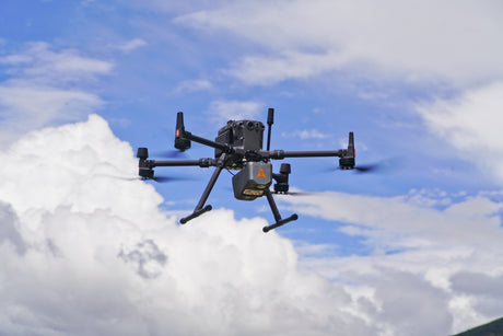
A directional Yagi antenna mounted high on a pole at a remote forestry site — the height-and-gain combination that often beats raw transmit power for long-baseline RTK.
Same wattage, different antenna — what actually changes
Every 3 dB of antenna gain doubles your effective radiated power. Every 6 dB doubles your range in free space. So at the same 5 W transmit power:
| Antenna on a 5 W radio | Acts like a stubby on a… |
|---|---|
| Quarter-wave stubby (the basic option) | 5 W radio (baseline) |
| Half-wave whip | 10 W radio |
| 5/8-wave (GAT24-class) | 16 W radio |
| Yagi (directional, aimed) | 50 W radio in the aimed direction |
A 5 W base radio with a good 5/8-wave whip on a mast can match or outperform a 15 W base with a stubby antenna — without the heat, battery drain, or amplifier strain. This is also why CHCNAV designs the iBase with a 5 W internal radio: paired with a proper external whip on the tripod, real-world range routinely matches or exceeds higher-power radios that ship with built-in stubbies.
Polarization — the easy way to lose 3 dB
UHF survey radios are vertically polarized. Whips on both base and rover need to point straight up. A 30° tilt costs ~1 dB; 60° costs ~6 dB; 90° (one vertical, one horizontal) drops the link entirely. A bent rover whip in transit, a base antenna leaning on a tripod, or a Yagi mounted slightly off-axis are all silent range-killers. Check antennas are plumb-vertical before troubleshooting anything else.
Cable losses — the silent power sink
Coaxial cable between the radio and the antenna eats some of your power before it reaches the air. At 450 MHz, losses vary dramatically by cable type:
- RG-58 (thin): ~30 dB per 100 m → ~1.5 dB lost per 5 m run. Acceptable for short jumpers; brutal on long mast feeds.
- RG-213 (thicker): ~14 dB per 100 m → ~0.7 dB per 5 m. Reasonable balance.
- LMR-400 (low-loss): ~9 dB per 100 m → ~0.45 dB per 5 m. The right choice for any mast install longer than a couple of metres.
For long mast runs, a cable upgrade often pays back more than a power upgrade.
Height beats power, every time
UHF range is dominated by line-of-sight. The horizon distance for an antenna at height h meters is roughly 4.12 × √h kilometers — so an antenna at 2 m sees 5.8 km, at 5 m sees 9.2 km, at 10 m sees 13 km. Both ends elevated combine. Raising your base antenna from a 2 m tripod to a 5 m mast typically extends range more than tripling your transmit power.
Repeaters and the latency cost
A repeater receives the base signal and retransmits it on the same or a different frequency, hopping over terrain or bridging to rovers beyond direct range. Each repeater adds latency — the repeater has to receive the full packet, then retransmit it — typically several hundred milliseconds per hop, more if the over-the-air rate is slow. Two repeaters in series can push latency past the 2-second age-of-corrections budget on slower channels. Prefer one hop with a high antenna over two hops with low ones. Repeaters cannot change protocol or data rate — keep the over-the-air rate consistent through the chain.
Troubleshooting Field Symptoms
Rover stays on float past 5–8 km
- Check antenna height on the base — line-of-sight failure is the #1 cause
- Check antenna, cable and connectors — a damaged whip, bent connector, or corroded coax can cost more signal than doubling your transmit power would gain
- Signal is too weak at distance — try GMSK if you're on 4FSK; GMSK is more robust at the edge of usable range
- Channel may be saturated — switch to a compressed format if both ends support it (DistLink, CMRx, Leica 4G), which roughly halves the bandwidth needed
Connected but no fix
- Verify protocol matches on both ends — TRIMTALK 450S, SATEL 3AS, and Pacific Crest are different protocols and the radios will not decode each other unless both are set to the same protocol or a compatibility mode
- Check channel frequency on both ends (radios sometimes step in 2.5 kHz increments that look identical on the menu but differ in hardware)
- Verify FEC and scrambling settings match exactly on both ends
- Confirm correction data format matches — RTCM 3.2, CMRx, DistLink, Leica 4G are all different and the rover has to be set to decode whatever the base is broadcasting. See our corrections guide for the format compatibility details
Fix oscillating between fixed and float on a "connected" link
- Classic symptom of a saturated channel — corrections piling up in the radio buffer past the rover's age-of-corrections threshold
- Check for poor sky conditions at base or rover — heavy canopy, buildings nearby, or low satellite count means few common satellites between base and rover, which causes the rover to drop in and out of fix even with a healthy radio link
- Switch to a compressed format if both ends support it (DistLink for CHCNAV-to-CHCNAV, CMRx between Trimble units, Leica 4G between Leica units) — roughly half the bandwidth of equivalent RTCM
- Move from GMSK to 4FSK if signal margin allows — doubles channel throughput
Base radio overheating or battery dying fast
- Drop transmit power — 35 W is rarely necessary; 10 W is usually plenty for <10 km in line of sight
- Switch GMSK to 4FSK if signal margin allows
- Turn FEC off if you have a healthy link — meaningfully less transmit time and heat
- Switch to a compressed data format if both ends support it (DistLink, CMRx, Leica 4G) — shorter packets mean shorter transmit bursts and less heat
Cross-brand setup will not link at all
- Before configuring anything, check what protocols, modulations, and data formats each radio actually supports — the base can only transmit what it has, and the rover can only decode what it has. Match both ends to settings that exist on both sides
- Start with the slowest universal setting: TRIMTALK 450S, GMSK, 4800 bps, 12.5 kHz, FEC off, scrambling off. Fewer features active means fewer settings that can mismatch
- Set the correction data format (RTCM 3.x is the most universal) — both base and rover must agree
- Once a fix is locked, optimize upward toward 4FSK and higher rates one variable at a time
- If the rover supports it, enable "Auto detect" or "Auto Rx" mode to let it discover the base configuration
Frequently Asked Questions
Why does my RTK rover stop fixing past 8–10 km even on flat ground?
Range is rarely a baseline-error issue at 10 km — it is almost always a radio link issue. Start with the antenna: is the base antenna high enough to clear the line of sight to the rover? Is the antenna vertical, undamaged, and properly seated? Check the cable and connectors next — a single corroded SMA connector or a damaged coax run can cost more signal than doubling your transmit power would gain. After hardware, look at the radio settings: try GMSK instead of 4FSK if you are at the edge of usable range, since GMSK handles weak signal far better. Forward error correction can also help if you are seeing dropped packets at distance. Transmit power is the last thing to reach for — most range problems are solved by raising the antenna and checking the connectors.
What is the difference between GMSK and 4FSK in UHF radios?
GMSK is a continuous-phase modulation that produces a clean, narrow spectrum and tolerates weak signals well — it is the most robust choice in noisy or marginal RF conditions. 4FSK encodes two bits per symbol by shifting between four discrete frequencies, which lets it carry more data than GMSK in the same channel width — typical SATEL 3AS or PacCrest 4FSK runs at 9600 bps in 12.5 kHz and 19,200 bps in 25 kHz with FEC off. GMSK rates depend on the protocol implementation and channel width: TRIMTALK 450S runs at 4800 bps in 12.5 kHz, while modern Pacific Crest ADL implementations support up to 9600 bps in 12.5 kHz and 19,200 bps in 25 kHz. In general, 4FSK runs the transmitter for shorter bursts to send the same correction message and generates less heat, making it the modern default for multi-constellation RTK. Use GMSK when range or signal robustness is more important than throughput.
What does TRIMTALK 450S actually mean — is it a radio, a modulation, or a protocol?
TRIMTALK 450S is a Trimble link protocol, not a piece of hardware. It defines how data packets are framed, error-corrected, and acknowledged over the air. TRIMTALK 450S runs on GMSK modulation at 4800 bps in a 12.5 kHz channel or 9600 bps in 25 kHz. Many third-party radios — SATEL, Pacific Crest, CHCNAV — implement TRIMTALK 450S as a compatibility mode so they can talk to a Trimble base or rover. The protocol, modulation, channel spacing, and FEC settings all have to match on both ends or the link will not lock.
Can I mix radio brands between my base and rover?
Yes, but only if both ends are configured to identical protocol, channel spacing, FEC and scrambling settings — and to a correction data format both radios support. Most modern radios — SATEL, Pacific Crest, Trimble TDL, CHCNAV — include compatibility modes for the major proprietary protocols (TRIMTALK 450S, SATEL 3AS, PacCrest 4FSK/GMSK/FST). On the data side, RTCM 3.x is the most universal format across brands; proprietary compressed formats like CMRx, DistLink, and Leica 4G generally only work within their own brand. The most common cause of "we cannot get a fix between brands" is a mismatch in FEC, scrambling, or data format, rather than the protocol itself.
Do I need forward error correction (FEC) turned on?
FEC adds roughly 30% overhead to your data stream — meaning the radio has to transmit longer to send the same correction message, which increases heat and power consumption. It is genuinely useful only at the edge of usable range or in heavy interference. For 35 W base radios in line-of-sight conditions under 10–15 km, FEC off with 4FSK at 9600 or 19200 bps is usually faster, cooler, and just as reliable. Turn FEC on if you start seeing dropped packets at long range or in dense urban environments.
How far can a 35 W UHF base radio realistically reach?
On flat, open ground with the base antenna mounted on a tripod at 2–3 m, expect 5–10 km. Raise the antenna to 5 m on a mast and you may reach 15–20 km. With a tall mast, a directional Yagi, or a repeater, 25–30 km is achievable for linear work like highway or rail corridors. Modern compressed protocols such as CHCNAV DistLink push effective range further at the same transmit power by reducing how much data has to fit in each second — published spec is 30 km on a 5 W iBase, and field reports under good conditions (open terrain, raised antenna, low RF noise) have shown 40 km or more. Range falls off sharply in trees, rolling terrain, or urban environments, where antenna height almost always matters more than raw transmit power.
What is the difference between UHF and 900 MHz ISM band for RTK?
UHF (typically 410–470 MHz) is the survey standard because it offers the best balance of range, antenna size, and propagation through vegetation and rolling terrain — practical reach is 5–30 km depending on power and antenna height. 900 MHz ISM (902–928 MHz) gives shorter range (typically 1–5 km), is more crowded with consumer devices like cordless phones and LoRa transmitters, and suffers higher path loss through trees and structures. For most professional Canadian surveying work, UHF wins on range and stability. 900 MHz finds its niche in short-baseline UAV operations and small-fleet machine control.
Closing Thoughts
UHF radio is not glamorous in 2026. It is sixty-year-old physics, dressed up with progressively smarter modulation and compression. But it is also the only correction delivery method that does not depend on a cell tower or someone else's network. For Canadian surveyors working highway corridors, mining sites, forestry blocks, agricultural fields, and the long stretches between towns, a properly configured UHF link is still the most reliable way to push centimeter-grade corrections from base to rover.
The principles, distilled: pick the channel width your radio supports, then pick the modulation that fits your range and throughput needs (4FSK for default, GMSK for marginal links). Use compressed formats like DistLink, CMRx, or Leica 4G when you can — they cut bandwidth roughly in half. Match every setting on both ends. Use antenna height and gain before transmit power. Turn FEC on only when you need it. And when you find a working link, write down the exact configuration — protocol, modulation, channel, baud, FEC, scrambling — because your future self will thank you.
At Latnet Technologies, we work with surveyors across Canada to specify, configure, and support UHF radio systems alongside the GNSS receivers they pair with. Whether you are running a single CHCNAV iBase on a tripod or a multi-repeater backbone for a highway corridor, the radio link is half the system — and getting it right is what turns a base-and-rover setup into a project that runs all day without surprises.
Need help configuring your radio link?
Latnet provides free consultation on UHF radio system design, channel selection, and CHCNAV iBase / DL8 / rover setup for Canadian survey crews.
Talk to LatnetTRIMTALK®, TRIMTALK 450S®, and TDL® are trademarks of Trimble Inc. SATEL® and SATEL 3AS® are trademarks of SATEL Oy. Pacific Crest® and ADL® are trademarks of Pacific Crest, a Trimble subsidiary. Leica® is a trademark of Leica Geosystems AG. References are for interoperability and informational purposes only and do not imply affiliation or endorsement.